What is USB-C?
I don’t know if you have ever been troubled by the dazzling data interfaces. Whenever I want to connect a certain device and can't find the cable that matches the device's interface anywhere, I look forward to the emergence of a certain interface to dominate the world.
In recent years, people have been calling for the man who is about to unify the world! Ah, no, that interface! Finally appeared! It is USB-C. What are we talking about when we say USB-C?
It should be noted here that when we talk about the USB-C socket, we should pay attention to distinguishing it from the interface specifications of USB2.0 and 3.0. The former refers to the interface type, and the latter refers to the interface specifications proposed by USB in different periods. When understanding USB-C, we must first understand the concept of USB. Here is a brief overview.
Origin of USB interface
In 1994, Intel and Microsoft initiated the International Standardization Organization, referred to as "USB-IF". The organization has developed a series of specifications and specifications for the Universal Serial Bus. Among them, the charging specification is the charging protocol we mentioned in the previous issue. In addition, they have also produced an adapted standard interface based on this specification. This is the origin of the USB interface.
The relationship between interfaces and protocols
Therefore, the evolution of the USB interface is always closely related to the update of the USB interface protocol. The physical characteristics of the interface are designed to adapt to a certain interface protocol. Only when the interface and interface protocol match successfully can data transmission or other operations be performed.
USB interface family
So, below, ZONSAN will give you a good introduction to the ever-evolving USB interface family.
From the name of USB-C, we know that USB-B and USB-A have been launched before, and they are usually called Type-A, Type-B, and Type-C. Let’s first understand what interface types USB has pushed.
USB-A, USB-B, and USB-C interfaces introduced by USB, each type may be divided into standard, mini, and micro according to size type. Let’s get to know the family members based on this picture:
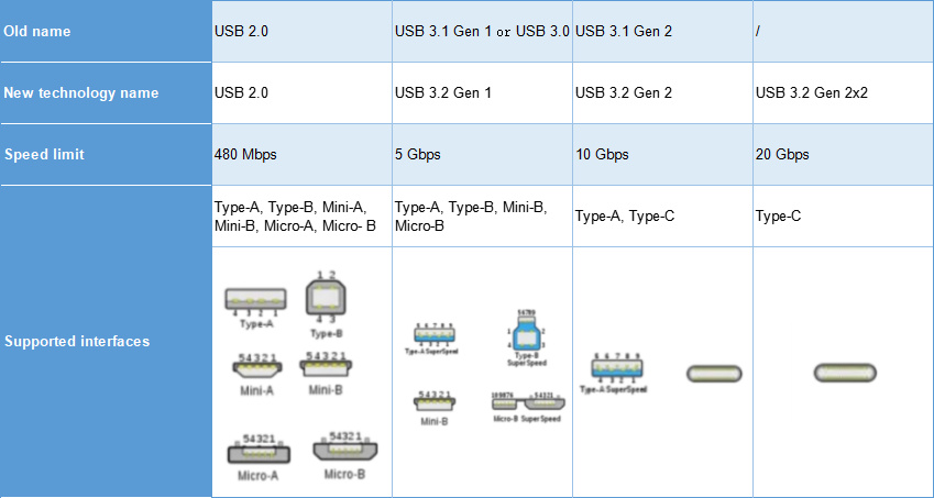
And the unification was completed when USB4 1.0 was released. In the release content of USB4 1.0 version f, it was stipulated that the USB-C interface would be the only designated interface, and it has been used until the recently released USB4 2.0

USB Type-C was proposed along with the USB 3.1 standard. Since it is a new form, TypeC does not have the problem of being "compatible" with old devices. In fact, the real promotion of USB Type-C started in 2015, when Apple’s MacBook was equipped with a USB Type-C interface. The first domestic manufacturer to use USB Type-C as a mobile phone interface was LeTV 1 (not Huawei) .
USB-C interface type
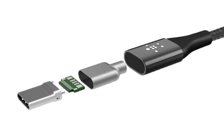
The emergence of USB-C makes these sockets basically the same in appearance, but in fact, there are still big differences between them. This difference is mainly reflected in the number of internal pins (pins, also called pins). , called Pin in English. It is the connection between the internal circuit of the integrated circuit (chip) and the peripheral circuit. All the pins constitute the interface of this chip.) The standard USB-C interface has 24PINs (pins), as shown below. shown.
Interface Type
Female head/female seat

Male/plug
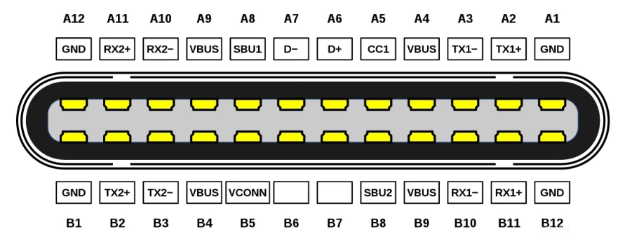
It can be clearly seen that the Pin function in the socket is symmetrical with respect to the center. The male plug is inserted into the female plug, and the pin functions are perfectly matched regardless of whether it is plugged forward or backward.
Interface pin
In the previous link, we talked about the division of the USB-C interface depending on the number of pins (PINs), and the number of pins (PINs) of the USB-C interface directly depends on which functions the interface needs to be applied to.
| Pin | Name | Function Description | Pin | Name | Function Description |
|---|---|---|---|---|---|
| A1 | GND | ground | B12 | GND | ground |
| A2 | SSTXp1 | SuperSpeed differential signal #1, TX, positive | B11 | SSRXp1 | SuperSpeed differential signal #1, RX, positive |
| A3 | SSTXn1 | SuperSpeed differential signal #1, TX, negative | B10 | SSRXn1 | SuperSpeed differential signal #1, RX, negative |
| A4 | VBUS | bus power | B9 | VBUS | bus power |
| A5 | CC1 | Configuration channel | B8 | SBU2 | Sideband use (SBU) |
| A6 | Dp1 | USB 2.0 differential signal, position 1, positive | B7 | Dn2 | USB 2.0 differential signal, position 2, negative |
| A7 | Dn1 | USB 2.0 differential signal, position 1, negative | B6 | Dp2 | USB 2.0 differential signal, position 2, positive |
| A8 | SBU1 | Sideband use (SBU) | B5 | CC2 | Configuration channel |
| A9 | VBUS | bus power | B4 | VBUS | bus power |
| A10 | SSRXn2 | SuperSpeed differential signal #2, RX, negative | B3 | SSTXn2 | SuperSpeed differential signal #2, TX, negative |
| A11 | SSRXp2 | SuperSpeed differential signal #2, RX, positive | B2 | SSTXp2 | SuperSpeed differential signal #2, TX, positive |
| A12 | GND | ground | B1 | GND | ground |
However, most USB-C interfaces on the market do not have so many. Manufacturers consider cost and market demand.
Considering this, some functions of the USB-C interface will be selected in the form of reduced pins. Let me give you a brief overview of the common USB-C interface types on the market.
| Type | Configuration pins | Common device interfaces | Function |
|---|---|---|---|
| 6PIN | Vbus, GND, CC1, CC2, GND, Vbus | Simple electrical appliances such as toys and electric toothbrushes | Only supports charging and discharging |
| 16Pin/12Pin | Eliminated TX1/2, RX1/28 pins | Mainstream wires and general digital products | No high-speed data transfer function |
| 24PIN (full PIN) | All pins | High-end gaming laptop | Standard USB-C port full function |
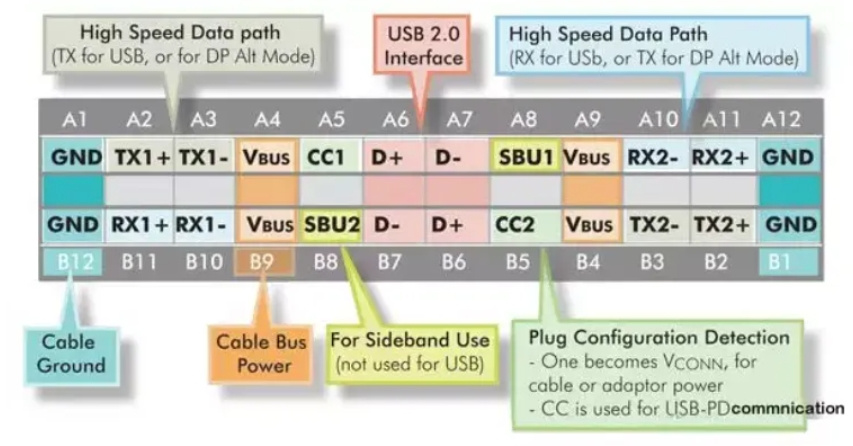
According to the number of pins of the current mainstream USB-C port, the physical appearance of the USB-C interface can be divided into three categories. They are 24pin (full pin), 16/12pin, and 6pin. Below are the details of these types.
24PIN
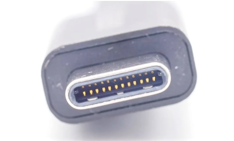
The 24PIN interface, also called the full PIN interface, is the standard interface of USB-C. It is common on some higher-configuration digital products (such as high-end gaming laptops). It is worth mentioning that the USB-C interfaces that currently support USB3.1 and above interface protocols are basically full of PIN configuration, especially those that support Thunderbolt 4 (Thunderbolt 4). protocol) interface digital electrical products.
Full PIN configuration generally means that the usage scenarios of the USB-C interface will basically cover all functions. With the development of technology and the improvement of people's living standards, more and more USB-C interfaces will be equipped with full PIN configuration, so that people can Enjoy a better experience brought by the standard USB-C interface.
16PIN

16Pin is currently the most mainstream USB-C socket. It is currently widely used in various Type-C cables, USB-C sockets of various charging equipment, commonly configured digital appliance USB-C sockets and other USB-C sockets.
Since the MCU (Microcontroller Unit; Microcontroller Unit) built into many common electronic devices currently does not support USB3.0 and only supports USB2.0, it would be a waste to use 24Pin TypeC, so there is a 16Pin TypeC.

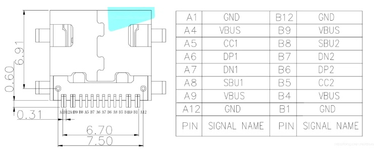
12PIN
What we call 16Pin TypeC and 12Pin TypeC are actually the same interface. 16Pin is generally the official name of the interface manufacturer and package, but it is commonly called 12Pin in daily life. This is because when the interface was designed, the two Vbus and GND wires at both ends of the TypeC female socket were put together. Although there are 16 wires from the interface, there are only 12 pads behind the socket.
6PIN
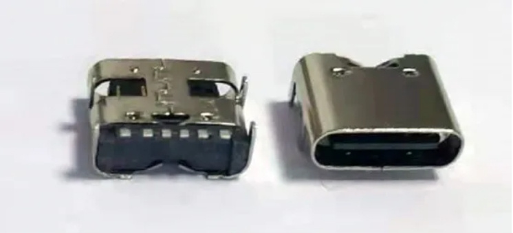
The 6PIN USB-C interface is often configured on some simple appliances such as toys and toothbrushes. The product positioning does not require USB communication and only requires USB power for charging. So 6Pin TypeC was born.

As shown in the figure, 6Pin TypeC only retains Vbus, GND, CC1, and CC2. There are two sets of GND and Vbus symmetrically distributed on both sides of the interface, which retains the anti-reverse insertion function, and the thick wire also makes it more convenient to transmit large currents.
CC1 and CC2 are used for PD device identification and carry USB-PD communication to request power supply from the power supply end. While power is being transferred, USB data transfer will not be affected.
USB-C role definition
From the perspective of power supply, the USB-C interface can be a power supply (Source) or a power consumer (Sink)) or a dual role (DRP). From the perspective of communication functions, the Type-C interface can be a downlink port (DFP) or an uplink port (UFP) or a dual role. For the functional role, it is determined based on the power supply role when connecting. When the power supply role is the power supply party, the functional role defaults to DFP; when the power supply role is the power consumer, the functional role defaults to UFP.
Let’s look at the power supply status under different role definitions through a table.
Power Role Communication Functions
Data role
DFP
The downlink interface is equivalent to the previous host;
UFP
It is the uplink interface, equivalent to the previous device;
Power role
SOURCE
It is a pure power supply party and will provide power to the sink;
SINK
It is a pure power consumer;
Sink&sours
Also known as DRP (Dual Role Port), it is a dual-role power supply device, which can be either SOURCE or SINK.
The data role and the power role are intertwined, and the roles can be dynamically switched through USB PD.
USB-C port application
As I introduced to you earlier, although USB-C is a descendant of the USB interface family, it has the innate advantages of the family's technology accumulation for generations. This makes USB-C have strong comprehensive performance when it comes out, and it has become the most widely used interface in the field. One of the interfaces.
Currently, digital products can be quickly charged through the USB-C interface, and many excellent fast charging products have been derived from this. In addition, USB-C’s powerful high-speed data transmission function plays an important role in some application scenarios in work and life, greatly improving efficiency. In addition, the application of USB-C interface can currently realize the transmission of different signals (video, audio, network, etc.), which expands the application space of this interface and makes the transmission of different signals convenient and efficient. Next, let’s take a look at what functions can be achieved through the USB-C interface?
We sorted out the corresponding functions of the 24 PIN pins of the standard USB-C interface, and summarized the current seven major application modules of the USB-C interface. Below are the details of its different applications.
Fast charging
USB Charging Standards History
In August 2014, the USB PD2.0 fast charging standard was released, which not only specified the USB Type-C interface as the only standard interface, but also gave this interface more functions, such as charging, data transmission, audio transmission, etc. In terms of charging, USB PD2.0 defines support for 5V3A, 9V3A, 12V3A, 15V3A, and 20V5A output, with a maximum charging power of 100W.
In November 2015, USB PD entered the PD3.0 fast charging era. There are three main changes in USB PD3.0 compared to USB PD2.0: a more detailed description of the device's built-in battery characteristics is added; the function of device software and hardware version identification and software update through PD communication is added, and the number Certificate and digital signature functions.
In February 2017, USB PD ushered in a major update with "minor fixes". USB PD3.0 PPS was released, adding a programmable power function (PPS) based on the PD3.0 standard. The PPS specification integrates the current two charging modes of high voltage and low current and low voltage and high current. The device can finely adjust the power supply output voltage according to the power demand. The amplitude modulation is 20mV, which is only one-tenth of the amplitude modulation of QC3.0. At present, PPS combined with charge pump has become a widely popular charging technology in the Android mobile phone camp.
In May 2021, USB PD crossed the 100W fast charging threshold, and USB PD 3.1 was released. The protocol is divided into two parts, one is the Standard Power Range (SPR), and the other is the Extended Power Range (Extended Power Range, EPR). In fact, SPR is actually the main part of the previous version of USB PD 3.0 protocol, which means that the maximum charging power of this part is still 100W; the additional EPR is based on this standard working range, greatly increasing the maximum power of fast charging. Expanded to 240W.
Currently, various types of fast charging products used in USB-C interfaces are developing rapidly. There are mobile power supplies rooted in outdoor life, such as the "Dianxiaoer" outdoor power supply that currently leads the international market in sales; sometimes hot-selling fast-charging chargers, especially the advent of gallium nitride, a new material, have become a binding has the important label of fast charging charger; some manufacturers are actively launching fast charging cables equipped with USB-C interface. Currently, 5A cables that support the full protocol are the focus of competition for this product.
Data transmission
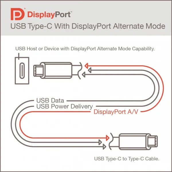
The USB-C port transmits video signals by switching to Alternative mode to transmit DP signals, or switching to HDMI Alt-Mode to transmit HDMI signals. Therefore, the USB-C interface currently supports DP Alt output, and currently supports video signals of the DisplayPort 1.4 protocol. It also supports HDMI Alt output, supporting protocols up to HDMI 1.4.
As for the specific principle, we have introduced the USB-C pins above. The four pins TX1, TX2, RX1, and RX2 are four pairs of differential signal transmission channels. When switching to DP Alt-Mode, these four pairs of differential signal transmission channels are used to transmit the four data channels of DP. The four-channel DP 1.4 can transmit two 4K+SDR+60Hz screens. However, these four channels are not required to enable transmission of DP signals at the same time. The specific application scenario depends on whether the channel needs to be occupied to transmit USB 3.1 data.
If you switch to HDMI Alt-Mode, these four pairs of differential signal transmission channels are the four data channels used to transmit HDMI signals. However, because it can only support HDMI 1.4b video signal transmission, it supports up to 420 4K 60Hz SDR or uncompressed 30Hz, but does not support HDR. Therefore, in most cases, the DP1.4 output by the host is converted into the higher HDMI 2.0 protocol through a converter chip to support 4k 60hz screens.
Nowadays, many manufacturers tend to reduce the number and types of interfaces in order to make their products more beautiful and save peripheral interface area. USB-C is the best choice for peripheral interfaces for digital products due to its better data compatibility. Therefore, USB-C to DP and HDMI video signal adapter products have widely appeared. Currently, such adapters basically support 4K 60Hz video signal output and can meet the basic needs of most users.
Audio transmission
In the past few years, headphones directly connected to the USB-C interface have been very popular on the market. We found that the USB-C interface can be connected to headphones for audio transmission. How is this done? The audio mode pin definitions are as follows:


CC1 and CC2 are used for PD device identification and carry USB-PD communication to request power supply from the power supply end. While power is being transferred, USB data transfer will not be affected.
USB-C role definition
From the perspective of power supply, the USB-C interface can be a power supply (Source) or a power consumer (Sink)) or a dual role (DRP). From the perspective of communication functions, the Type-C interface can be a downlink port (DFP) or an uplink port (UFP) or a dual role. For the functional role, it is determined based on the power supply role when connecting. When the power supply role is the power supply party, the functional role defaults to DFP; when the power supply role is the power consumer, the functional role defaults to UFP.
Let’s look at the power supply status under different role definitions through a table.
| Power role | Connect initial communication function role | illustrate |
|---|---|---|
| Source | DIP | interface for power supply |
| Sink | UIP | interface for charging |
| Dual Role Port.DRB | DFP or UFP | The interface can be either a power source or a power consumer, switching between dual roles (DRP) (DEP or UPP) on the connection, which can only be determined when a device is connected. When the connected device is the power provider, this interface is the power consumer; when the connected device is the power consumer, this interface is the power provider; when the connected device also has dual roles, this interface may be the power provider or the power consumer. It is a power consumer. |
Data role
DFP
The downlink interface is equivalent to the previous host;
UFP
It is the uplink interface, equivalent to the previous device;
Power role
SOURCE
It is a pure power supply party and will provide power to the sink;
SINK
It is a pure power consumer;
Sink&sours
Also known as DRP (Dual Role Port), it is a dual-role power supply device, which can be either SOURCE or SINK.
The data role and the power role are intertwined, and the roles can be dynamically switched through USB PD.
USB-C port application
As I introduced to you earlier, although USB-C is a descendant of the USB interface family, it has the innate advantages of the family's technology accumulation for generations. This makes USB-C have strong comprehensive performance when it comes out, and it has become the most widely used interface in the field. One of the interfaces.
Currently, digital products can be quickly charged through the USB-C interface, and many excellent fast charging products have been derived from this. In addition, USB-C’s powerful high-speed data transmission function plays an important role in some application scenarios in work and life, greatly improving efficiency. In addition, the application of USB-C interface can currently realize the transmission of different signals (video, audio, network, etc.), which expands the application space of this interface and makes the transmission of different signals convenient and efficient. Next, let’s take a look at what functions can be achieved through the USB-C interface?
We sorted out the corresponding functions of the 24 PIN pins of the standard USB-C interface, and summarized the current seven major application modules of the USB-C interface. Below are the details of its different applications.
Fast charging
| Time | Protocol standards | Interface | Charging specifications |
|---|---|---|---|
| 2010 | USB BC1.2 | USB Type-A | 5V 1.5A |
| 2012.7 | USB PD1.0 | USB Type-A, USB Type-B | Unknown |
| 2014.8 | USB PD2.0 | USB Type-C | 5V 3A, 9V 3A, 15V 3A, 20V 2.25A, 20V 3A, 20V 5A |
| 2015.11 | USB PD3.0 | USB Type-C | 5V 3A, 9V 3A, 15V 3A, 20V 2.25A, 20V 3A, 20V 5A |
| 2017.2 | USB PD3.0 PPS | USB Type-C | 5V 3A, 9V 3A, 15V 3A, 20V 2.25A, 20V 3A, 20V 5A PPS: 3.3V-5.9V 3A, 3.3-11V 3A, 3.3-16V 3A, 3.3-21V 3A, 3.3-21V 5A |
| 2021.5 | USB PD3.1 | USB Type-C | 5V 3A, 9V 3A, 15V 3A, 20V 3A, 20V 5A PPS: 3.3-5.9V 3A, 3.3-11V 3A, 3.3-16V 3A, 3.3-21V 3A, 3.3-21V 5A EPR: 28V 5A, 36V 5A, 48V 5A AVS: 15-28V 5A, 15-36V 5A, 15-48V 5A |
In August 2014, the USB PD2.0 fast charging standard was released, which not only specified the USB Type-C interface as the only standard interface, but also gave this interface more functions, such as charging, data transmission, audio transmission, etc. In terms of charging, USB PD2.0 defines support for 5V3A, 9V3A, 12V3A, 15V3A, and 20V5A output, with a maximum charging power of 100W.
In November 2015, USB PD entered the PD3.0 fast charging era. There are three main changes in USB PD3.0 compared to USB PD2.0: a more detailed description of the device's built-in battery characteristics is added; the function of device software and hardware version identification and software update through PD communication is added, and the number Certificate and digital signature functions.
In February 2017, USB PD ushered in a major update with "minor fixes". USB PD3.0 PPS was released, adding a programmable power function (PPS) based on the PD3.0 standard. The PPS specification integrates the current two charging modes of high voltage and low current and low voltage and high current. The device can finely adjust the power supply output voltage according to the power demand. The amplitude modulation is 20mV, which is only one-tenth of the amplitude modulation of QC3.0. At present, PPS combined with charge pump has become a widely popular charging technology in the Android mobile phone camp.
In May 2021, USB PD crossed the 100W fast charging threshold, and USB PD 3.1 was released. The protocol is divided into two parts, one is the Standard Power Range (SPR), and the other is the Extended Power Range (Extended Power Range, EPR). In fact, SPR is actually the main part of the previous version of USB PD 3.0 protocol, which means that the maximum charging power of this part is still 100W; the additional EPR is based on this standard working range, greatly increasing the maximum power of fast charging. Expanded to 240W.
Currently, various types of fast charging products used in USB-C interfaces are developing rapidly. There are mobile power supplies rooted in outdoor life, such as the "Dianxiaoer" outdoor power supply that currently leads the international market in sales; sometimes hot-selling fast-charging chargers, especially the advent of gallium nitride, a new material, have become a binding has the important label of fast charging charger; some manufacturers are actively launching fast charging cables equipped with USB-C interface. Currently, 5A cables that support the full protocol are the focus of competition for this product.
Data transmission

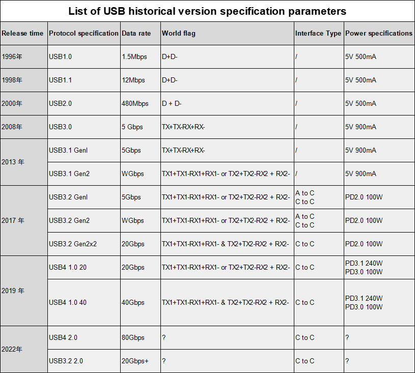
In 1996, the USB interface was born, which used D+D- wire cores for data communication, laying the foundation for future generalization.
In 2000, USB was updated to the USB2.0 version, which quickly became popular on a large scale with a speed of 480Mbps. It is also the most commonly used interface standard today.
In January 2008, USB3.0 was released, and the data transmission was changed to TX+TX-RX+RX- wire core. The transmission rate increased significantly from 480Mbps to 5Gbps, and the read and write speed exceeded 100 megabits per second, which brought a qualitative leap.
In July 2013, USB 3.1 was released, doubling the maximum speed to 10Gbps, and the familiar USB-C interface was also born at this time. There is a trick here. USB-IF renamed the old USB 3.0 to USB 3.1 Gen 1, and the newly released USB 3.1 is called USB 3.1 Gen 2. Ordinary consumers are beginning to get confused.
In September 2017, USB3.2 came again. Although the version number has not changed much, it supports the simultaneous use of the upper and lower pins of the USB-C interface. Two sets of high-speed channels can be used at the same time, and the maximum rate has doubled to 20Gbps. According to the latest published specifications, the USB3.0 and USB 3.1 version naming will completely disappear and be unified into the USB3.2 sequence. The three will be renamed USB3.2 Gen1, USB3.2 Gen2, and USB3.2 Gen2x2 respectively.
In September 2019, USB4 was officially released, with a maximum transfer rate of 40Gbps, the same as Thunderbolt 3. USB4 has two specifications, namely USB4 40 with a maximum bandwidth of 40Gbps and USB4 20 with a maximum bandwidth of 20Gbps. Consumers need to understand that USB4 40 is the full-blooded interface.
In September 2022, the USB4 2.0 standard will be exposed in advance, with the maximum speed increased to 80Gbps and a new data architecture. The USB PD fast charging standard, USB Type-C interface and cable standards will also be updated simultaneously.
There are currently many products with high-speed data transmission functions applied to USB-C interfaces, mainly including some external storage devices (such as high-speed solid-state drives, high-speed transmission cables, and interfaces directly used in some high-end notebooks.
Video transmission

Currently, USB 3.0 and above as well as USB-C interfaces with Thunderbolt 3 and Thunderbolt 4 protocols support video transmission. So can this type of USB-C port be used for video transmission? What is the integration relationship between USB-C, HDMI and DP?
The USB-C port transmits video signals by switching to Alternative mode to transmit DP signals, or switching to HDMI Alt-Mode to transmit HDMI signals. Therefore, the USB-C interface currently supports DP Alt output, and currently supports video signals of the DisplayPort 1.4 protocol. It also supports HDMI Alt output, supporting protocols up to HDMI 1.4.
As for the specific principle, we have introduced the USB-C pins above. The four pins TX1, TX2, RX1, and RX2 are four pairs of differential signal transmission channels. When switching to DP Alt-Mode, these four pairs of differential signal transmission channels are used to transmit the four data channels of DP. The four-channel DP 1.4 can transmit two 4K+SDR+60Hz screens. However, these four channels are not required to enable transmission of DP signals at the same time. The specific application scenario depends on whether the channel needs to be occupied to transmit USB 3.1 data.
If you switch to HDMI Alt-Mode, these four pairs of differential signal transmission channels are the four data channels used to transmit HDMI signals. However, because it can only support HDMI 1.4b video signal transmission, it supports up to 420 4K 60Hz SDR or uncompressed 30Hz, but does not support HDR. Therefore, in most cases, the DP1.4 output by the host is converted into the higher HDMI 2.0 protocol through a converter chip to support 4k 60hz screens.
Nowadays, many manufacturers tend to reduce the number and types of interfaces in order to make their products more beautiful and save peripheral interface area. USB-C is the best choice for peripheral interfaces for digital products due to its better data compatibility. Therefore, USB-C to DP and HDMI video signal adapter products have widely appeared. Currently, such adapters basically support 4K 60Hz video signal output and can meet the basic needs of most users.
Audio transmission
In the past few years, headphones directly connected to the USB-C interface have been very popular on the market. We found that the USB-C interface can be connected to headphones for audio transmission. How is this done? The audio mode pin definitions are as follows:

The TYPE-C specification defines two accessory modes, audio mode (the audio mode here is a 3.5mm analog audio adapter) and debugging mode. In audio mode, the USB-C interface can ensure smooth transmission of audio signals. Devices that implement audio mode will perform Ra lowering on both CC1 and CC2. When the host detects that both CCs of the connected device are Ra, it will consider that the USB-C interface is connected to an audio device.

How USB-C Audio Mode Works - Passive 3.5mm to USB Type-C Adapter - Unipolar Detection Switch
Other transmission purposes
PoE
The current technology can perform PoE transmission through the USB-C interface. How is this implemented?
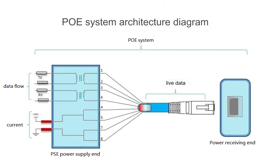
First, let’s understand the concept of PoE. PoE (Power over Ethernet) refers to a technology that transmits power through network cables. It uses existing Ethernet to simultaneously transmit power to IP terminal devices (such as IP phones, APs, IP cameras, etc.) through network cables. For data transmission and power supply. At present, there are unified standards for PoE power supply, IEEE802.3af, IEEE802.3at, and IEEE802.3bt. Three different protocols allocate different power to terminals.

The technical principle is as follows: The PoE system consists of PSE (Power Sourcing Equipment) and PD (Powered Device) power receiving ends connected through the power interface. PSE is a device used to provide power to other devices, and PD is a device used to receive power in a PoE power supply system. The PSE delivers current to the power interface by applying voltage to the network cable. The power interface is the physical node where the network cable connects the PSE and PD. The standard Ethernet interface has eight connecting wires, which can be divided into four differential pairs. When power transmission is required, different differential channel pairs are selected for power transmission according to the output power of the PSE. Then the power and data are processed through the adapter chip, and the current and other data signals are transmitted to the USB-C corresponding pin channel respectively. PD equipment, in this process, PSE and PD follow the operating steps shown in the figure above.
It is worth mentioning that there are already some manufacturers in the world developing this kind of product. For example, the "PD-USB-DP60 adapter" being developed by Microchip can use this product to use Ethernet to USB -C Host provides power and data.
Network
USB-C network data transmission technology is actually just a sub-application of PoE technology. In this case, there is no need to transmit power in the network cable. It only needs to pass the network signal through the chip in the converter to bridge the network signal to the PD device. So what is bridge networking technology?
Network bridging technology, as the name suggests, is the bridging technology of the network. It is divided into two bridging modes: wireless and wired. USB-C network data transmission mainly uses wired network bridging technology. The chip in the adapter is used to connect the network cable interface Rj 45 and USB The -C interface builds a bridge so that network signals can be transmitted to the terminal device. In this process, the USB-C network port adapter acts as an "external network card".
Frequently Asked Questions
1. Can all functions of a USB-C interface with a full PIN be used?
Answer: Not necessarily. There are two situations where full functions may not be used. One is that the full PIN interface produced by the merchant only looks like this, and there is no wire core connected with the corresponding function inside. The other situation is the usage scenario of the device connected to the interface. Not all its features are supported or available.
2. The current USB-C interface is already so versatile, will the appearance not change?
Answer: No, the physical appearance and functions of the USB interface change with the update of the USB protocol. Although the current interface is very complete, if the protocol changes in the future and more powerful and comprehensive functions are expanded, the appearance may also change. Changes will occur to accommodate the protocol.
3. Can the A to C cable support PD fast charging?
Answer: Generally it is not supported. Manufacturers represented by Xiaomi have launched original chargers and data cables for mobile phones in recent years. By adding special pins to the USB-A port, CC output can be provided at the USB-A port to achieve fast PD. Charge.
4. How to find out how much power the C2C wire supports?
You can't tell, unless there is an output power mark on the cable, you can only evaluate the power supported by the cable through an evaluator.
ZONSAN Summary
As the most comprehensive and versatile interface type at present, the USB-C interface has an increasing market share. The recently launched USB 4.0 also officially announced that USB-C will be the only designated interface, so In the near future, the USB-C interface will be more and more widely used in our lives, and with the improvement of technology and living standards, the experience brought by the USB-C interface will become better and better.